Best Available Technologies for Liquid Storage Tanks
Dr. ir. Erik Jeroen Eenkhoorn
Technical scientific designer (PhD, MSc, MBA)
Hengelo (O), The Netherlands
ABSTRACT
There are basically two different designs and constructions of tanks, i.e. fixed and floating roof tanks. Both types of tanks have become subject to additional provisions. These additions provide a predictable indication of the imminent changes in “Best Available Technologies” for the storage of large volumes of especially dangerous liquids. Although tanks are envisaged to store and contain liquid only, the entire tank construction usually also contain substantial volumes of vapour saturated air. This paper analyses both the “best liquid containment” technology as well as the “best vaporization avoiding” technology. Historically technology improvements in liquid storage focused on symptom mitigation rather than on elimination of the cause of a problem. Resolutions as presented in this paper qualify as “alternative and different” rather than “add-on’s and extra”.
KEY WORDS
Cairbag, Floating roof, Best Available Technology, Double Hull, Vaporisation avoidance, Emission-free liquid storage.
INTRODUCTION
Permanently installed, large tanks have been used for over a century to store large volumes of liquids, especially hydrocarbons (fuels) and chemicals. Such tanks generally comprise a “floor”, a cylinder-shaped side wall or “shell” and a “roof”. There are two types of roofs; fixed and (“external”) floating roofs. See pictures 1 and 2 respectively. Usually the mentioned parts of tanks made of metal, mostly steel and are commonly coated primarily to delay corrosion of this steel.
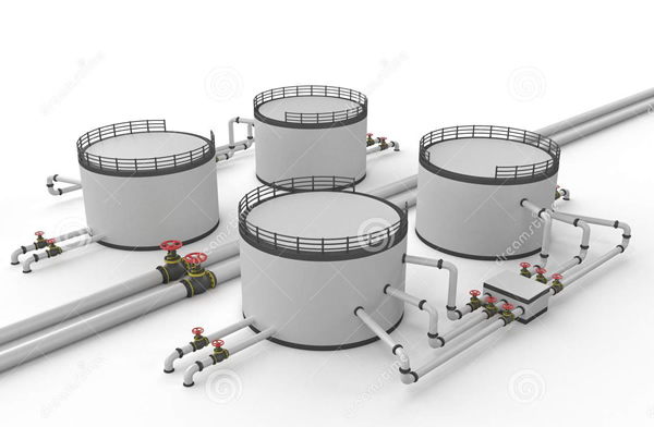
Picture 1. Schematic of four fixed roof tanks.
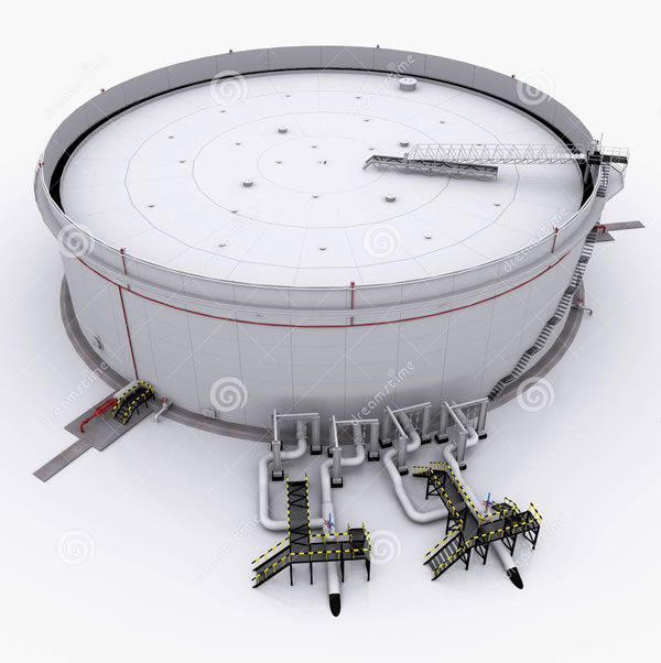
Picture 2. Schematic of one external floating roof tank.
The mentioned tank parts, except for the roof, are in contact with the liquid and have an obvious “containment function”. The liquid containment of tanks will be analysed first.
The roof does not have a (direct)containment function. So, what is the function of the roof of a storage tank? Answer:
- To prevent “things” falling out of the sky into the liquid.
- To prevent liquid or vapours thereof to escape from the tank
- To enable operators to walk and work on it, possibly using instrumentation and provisions positioned on the roof to enable such.
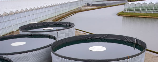
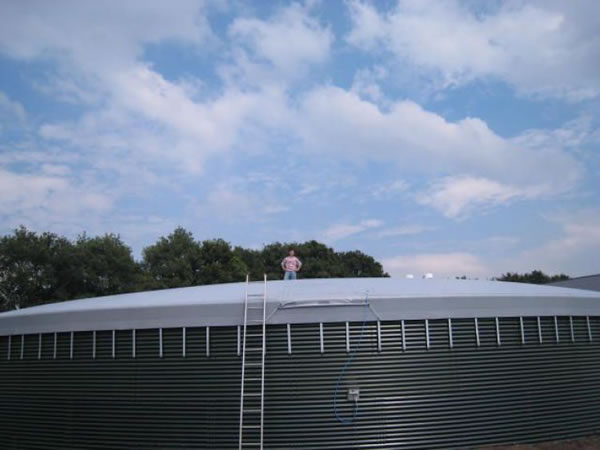
Water storage tanks at farms, generally, can be of the “open top” type. Rain falling into such tank, or water-damp evaporating from the tank is not a problem while there are no operational nor “working at heights” requirements making a roof necessary. See also picture 5.
The functional relationship of tank roofs with vaporisation avoidance and vapour containment and emissions will be analysed secondly hereinafter.
ANALYSES OF FLOORS AND SHELLS
Fundamentally, a liquid storage tank provides for the first or prime containment of the liquid. Only in case of a failure of this prime containment function, a bund-wall and a geo-textile-based containment are meant to be in place, as a “second line of defence”. See example in picture 3. This applies for both mentioned types of tanks. These secondary containment provisions are to ensure containment of any leaked or spilled liquids. The risk of a catastrophic floor or shell failure of the tank is considered very small. The, short-term, adverse environ-mental impact of a liquid filled bunded area or a soaked sub-soil is thus apparently considered acceptable. A quick calamity response is hereby assumed to be possible, to happen and to be effective. “Double hull” containment, which is for example mandatory in internal dangerous liquids carrying ships (see picture 4), or in small volume (diesel) storage tanks at farms, is not applied in large volume dangerous liquid storage tanks.
The life-cycle features of bunded areas
A bund-wall is firstly exposed against permanent weather conditions and to a (changing) climate exposure. Bund-walls, identically to (Dutch) dikes generally dry-out and deteriorate in their liquid holding capacities. The withstanding capabilities of bund-walls against calamity wave impacts or tank failures due to “topping” are often questionable. Bund-walls are not provided with any form of (continuous) conditioning monitoring or alarm raising equipment. Bunded areas generally accommodate more than one storage tank and require substantial surface areas to meet the volumetric containment requirements. The first aspect is risk enhancing and the second aspect is economically less attractive. The use of bunded areas as second containment being “the best available” is hence questionable. What are the alternatives?
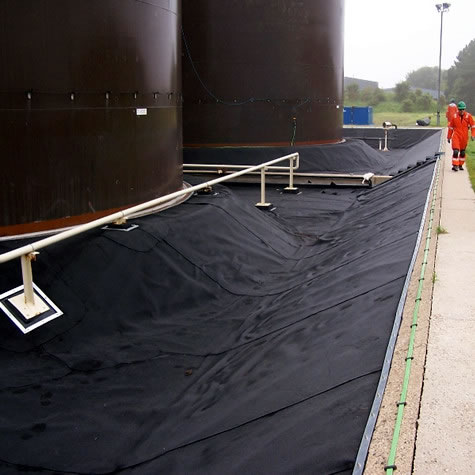
Picture 3, Example of a bunded area, here with geo-textile protection
A permanently available “double hull” containment is commonly applied in applications other than storage tanks. Such double hull applications are technically “proven” and often mandatory by law and legislative regulations (permits).
“Double hull” technology
The current state-of-the-art “double hull” technology as applied in (stationary and mobile) dangerous liquid holding tanks is typified by:
- Both hulls generally being made of (identical) steel, and of
- Space in between the two hulls.
This results generally in (too) heavy and expensive constructions, in (too) much loss of payload and in a space in between the two hulls. This space will be filled with flammable or even explosive vapours in due course. Most importantly however is that the addition of a second hull, identical to the first hull, hardly mitigates the risk of a catastrophic failure. This is due to the corrosion rates being equal for both hulls and for the likely deterioration of the corrosion conditions because of the space between the hulls. In (mobile) collision situations or at the impact of a rigid foreign object a double hull provides no more protection than a (slightly thicker) single hull would do.
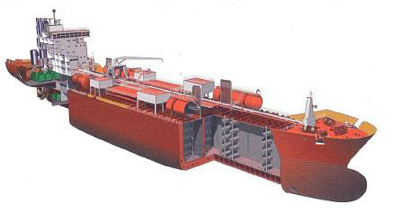
Picture 4, A bunker ship double steel hull example
These disadvantages have been avoided by the current state-of-the-art “double hull” technology of open top water tanks. Such water tanks, in compliance with API-650, ref [6}, have a virtually non-deformable (metal) outer shell providing the required strength and an inner shell made of a deformable liquid-tight elastomer foil. See picture 5. The elastomer foil cannot corrode and is impact resistant through its (polyamide “Kevlar”) carrier and through deformability. Furthermore, there is no space between the outer metal and inner foil shell.
Picture 5, Open-top “double hull” water storage tanks with metal outer shell and inner elastomer foil.
The best double hull technology
LINERBAGS
The double hull technology as applied in for example water tanks is a “better” technology as the version applied in ships and small dangerous liquid holding tanks, as:
- This a relatively cheap manner to create permanent double containment security, with a negligible loss of the payload capacity of the tank.
- The inner hull is easy to install (and to remove), hence easily replaceable by an inner hull made of a different material. Such different material is selected on its compatibility with a new different kind of liquid requiring to be stored in the same outer hull.
- There is no space left in between the two hulls, which space may pose a risk of becoming a hazardous area.
- The inner hull can be completely shop (pre-)fabricated, tested and installed in one piece (within a very short shut-down period of the tank). This also significantly reduces the exposure of labour to the site related risks of working.
- Double hulls allow for leak detection to be installed in between the floors of the two hulls, thereby allowing for immediate detection of a leak in either of the floors, if such would occur.
- Makes coating or “lining” of the inner tank shell and floor obsolete as the liquid has no longer any contact surface with the outer hull. The corrosion protection quality of an inner hull is much better as such quality of a spray(-gun applied) coated lining, primarily because of the possible higher thickness and strength of the inner-hull material and because of the prefabrication versus on site appliance quality differences.
- A strong but deformable inner hull is “bullet proof” and offers generally less risk of failure in case of an impact by a sharp rigid object.
- May provide cost effective cleaning solutions or may even make cleaning obsolete.
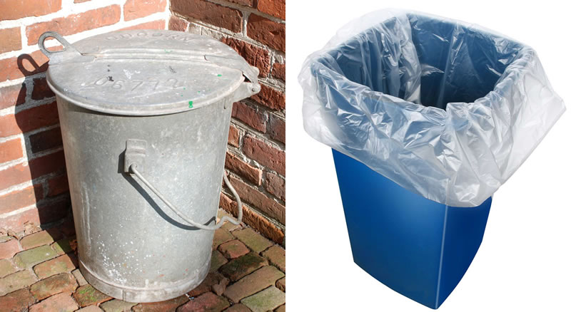
Pictures 6, example of technology improvement in (garbage) storage. (left): as “was”, (right): as “is”
Conclusion for bulk liquid storage tanks:
The proven “bag-in-box”, flexitank, mega-inliner, water tank technology is obviously available and better than single hull or double steel hull applications as in mobile liquid tanks as in ships.
The “inner hull” or “Linerbag” not only provides a better containment technology for all of the above detailed reasons but also protects the (outer) steel tank against stored liquid endured corrosion processes. The “inner hull” or “Linerbag” allows for applying a material with better insulation features to reduce the heat losses of the tank in case of storing a product requiring heating. The “inner hull” or “Linerbag” allows for air chamber provisions, not only do such enable the unmanned installation but they may also serve to reduce stresses and strains in the outer (steel) tank shell and floor in cases of earthquakes. Even options of inserting water, as cooling medium in cases of fires, in between the inner and outer hull may be considered. The option of an inflatable wedge-shaped floor, to enhance flow-out conditions for the liquid, may be considered.
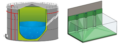
Figure 7, (left) Open-top Linerbag in fixed roof tank, (right): inflated channels in Linerbag shell to enhance installation features.
Tank safeguarding functions are taken care of by dedicated provisions not being in use for normal operational functions. Hence, the following shall be considered. A second hull shall not be qualified as a safety device but shall be a basic operational necessity. The second hull application allows for dedicated safety provisions like leak detection. This enables the possibility of continuous safeguarding and timely responses to deteriorating situations.
Multiple Linerbags of the enclosed type.
Finally, Linerbags of an enclosed version, may allow for installing more than one Linerbag, i.e. “Multiple Linerbags”, see figure 8, and use these simultaneously or alternatingly for the storage of the dedicated products for each, without having to do any cleaning in between.
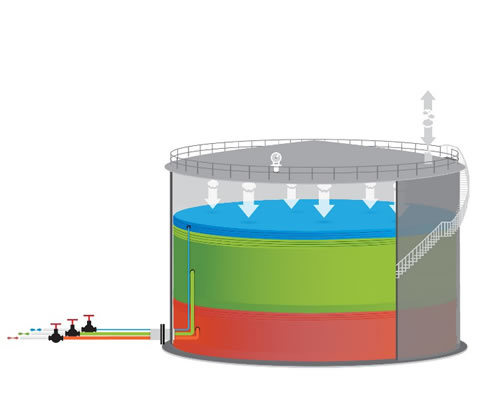
Figure 8, Details of Multiple Linerbag products
A multiple Linerbag system allows for more than one Linerbag to be present inside a storage tank, with each Linerbag having own in- and outflow provisions (hose based) and allowing for all necessary metering and safeguarding. Each Linerbag inside a fixed roof storage tank can be dedicated to a specific client and to his (/her) specific product to be stored whereby storage of a certain quantity of such product by the client is possible as long the maximum total working volume of the tank is and will not be reached over the storage period. The storage of different products for different clients is best realised when the to-be-stored products are very similar and not harmful to each other. When the to-be-stored products are not subject to aging or deterioration, like almost all fuels, the Linerbag components do not require to be cleaned. Cleaning becomes only mandatory when a tank is to store subsequent alternation liquids for different clients when no contamination of one product with another is allowed.
The big advantage of using multiple Linerbag systems is obtained in commercial storage. Where only one product can be stored in anyone tank currently, there can be more than one product stored simultaneously thus creating more commercial flexibility in commercial storage. Equally, clients wishing to store a certain liquid volume which is only a fraction (< 100%) of the tank volume, can allow for the balance of the tank volume to be rented to another user.
Cleaning cost may be avoidable. Besides the economic and financial advantage, tanks may not lose any rental time due to outstanding cleaning, Furthermore, there is no environmental impact of cleaning anymore.
New tank terminals may be designed on the basis of less but larger volume tanks, using multiple Linerbags in each tank. This requires (far) less investment than building new tank terminals with more smaller tanks. As the Multiple Linerbag of the enclosed type also avoid any and all emissions of such tanks, savings by not having to install vapour recovery units may be possible.
Analyses of roofs.
Sealing quality
The fixed and floating types of roofs as in pictures 1 and 2 respectively, are on a “stand-alone” basis apparently “not good enough” for liquids with a “dangerous” qualification. Apparently, the emissions of tanks with such single roofs and safety aspects are considered to be inadequate. Not only is the sealing quality of a rim seal insufficient, the seal and roof construction allow for entrapment of vapours allowing for “rim seal fires”. See pictures 9. This fact has resulted in a large industry of rim seal fire detection and firefighting equipment.
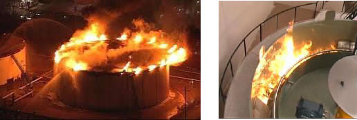
Picture(s) 9, Rim seal fires (examples)
Fixed roof tanks are therefor often provided with an extra internal floating roof while external floating roof tanks are provided with a so called “eco-dome”. A kind of “double roofing” is thus created. The “double roof” implementation, while the roof has no liquid containment function, on tanks which are not “double hull” is hence remarkable, to say the least.
Vaporization and vapour containment
At this point, it is interesting to address the subject of vaporization of stored (dangerous) liquids. Storage tanks which are only partially filled with liquid, also contain “free” air. This air becomes, is, saturated with vapours originating from the stored liquid, usually at vapour saturation conditions.
The presence of vapours inside a storage tank is not so much a problem during stationary storage, especially so of stored products with a low vaporisation level. Vapours are a concern when these become an emission for the obvious environmental impact consequences. The liquid owner may however be more concerned over the loss of product, hence the financial loss such emissions constitute. “No loss” is the best option.
Vapour emissions commonly occur when a storage tank is filled with liquid and, consequently air, vapours are expelled from the tank, through “breathing devices”, to the outside. This was already considered to be “not good”, certainly not “best”, as is confirmed by the large scale of vapour recovery systems being applied. Vapour recovery systems require often to be complex to ensure recovery of the large variety of vapour components and of flow rates. These systems are much more complex than a tank storing liquid. Fundamentally, it cannot be “good” to allow liquids to vaporize and then to convert such vapours back to liquid, at high cost and with much operational involvement. Secondly, liquids continue to vaporize until the vapour saturation pressure is reached. Withdrawing vapours from an enclosure, by a vapour recovery system, consequently, leads only to more vaporisation. Vaporisation of liquids in a storage tank is hence “better” to be prevented then allowed to exist (on a permanent basis). The presence of free air enabling vaporization shall thereto be avoided by design and construction of the tank.
Double roofs applications improve the containment of vapours and thereby the emission of such. The vapours are “trapped” in between the lower roof floating on the liquid surface and the upper roof remaining in a fixed position on the tank. The space in between the two roofs will get (saturated) vapour filled over time. The speed at which this space is vapour filled depends (besides the vapour pressure of the subject liquid) on:
- the quality of the rim seal of the lower roof,
- the vapour tightness of the panels of which the internal floating roof or the eco-dome is build,
- the frequency of changing the liquid level (volume) of the tank, and
- the frequency with which the lower roof lands on its “legs” and the non-liquid filled space underneath the lower roof becomes vapour filled.
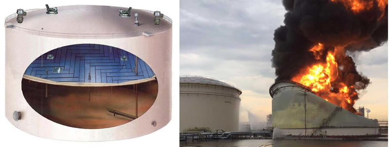
Pictures 10 (left) a fixed roof tank with an internal floating roof, (right) a lightning caused fire in a fixed roof tank with internal floating roof. (Singapore, Jurong 2016)
However, vaporisation still occurs, and emission mitigation is only possible with the continued use of vapour recovery from the space in between the two roofs. The flow rate of such vapours and hence the required operational range of the vapour recovery system varies substantially between normal, stationary conditions and tank liquid fill operations, when the volume of the space in between the two roofs reduces.
Wear and tear of rim seals
Rim seals are designed and fabricated based on both wear and tear resistivity and on sealing requirements. See pictures 11. The seal material has therefor to be both wear resistant (“hard”) and soft for a proper sealing function. Rim seals are attached to the internal or external floating roofs and have to move relatively to the inner tank wall in case of a volume change of the stored liquid. Rim seals are by design subject to wear and tear and are therefore made rigid and virtually non-deformable. However, rim seals perform their sealing functionality much better when not subjected to wear and tear. Rim seals are designed and constructed to scrape along the inner tank wall during filling and emptying of the tank. Rim seals perform their sealing functionality much better when they do not have a simultaneous scraping function.
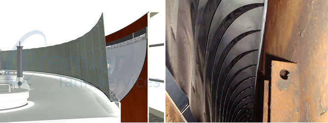
Picture(s) 11, Rim-seal (examples)
Non-deformable construction.
Panels.
Besides liquid to vapour losses passing by rim-seals, there are also vapour losses over the joints of panels. Non-deformable metal or glass-fibre panels are used to construct internal floating roofs and eco-domes. (see picture 12). Panels are used for construction and installation aspects, they must for example be able to pass through a manhole in case of an internal floating roof. From a vaporisation point of view, a “seamless” cover of the liquid surface would be “better”.
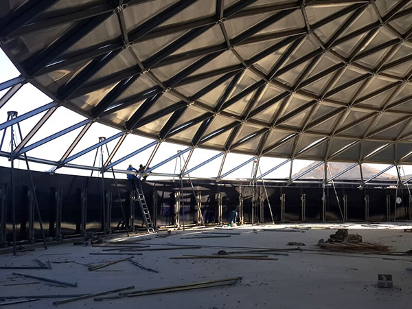
Picture 12, Panel constructed eco-dome
Legs.
Internal and external floating roofs have to land on “legs”. These legs are to ensure that the roof is supported in case the tank is liquid filled below a specified minimum volume. The limitation of a roof descending to some at least 1,5 to 2 meters over the tank floor at the withdrawal of the last liquid volumes from the tank, avoids interfaces with possible tank internal provisions and devices (like piping and mixers) and allows for working space in case of maintenance. This space will however become (air and) vapour filled in the process of final liquid withdrawal, which vapours create hazards as well as a likely source of emission.
Confined spaces
Double roofs and legs supporting floating roofs create confined spaces. Such confined spaces are highly undesirable not only from a fire and explosion safety but also from a safe and healthy working conditions point of view. Avoiding such spaces by design and construction and avoiding having to work in such spaces by operations and maintenance excellence is therefore “better”.
INFLATABLE INTERNAL FLOATING ROOF, iifr
Inflatable internal floating roofs, iifr’s avoid any and all contact between stored liquids and air and thus avoid that the liquid can evaporate. An iifr consists of an inner inflatable disc, made of a 3D or point-jointed double layer thermoplastic (or rubber) material, which becomes rigid trough inflation. This disc part is provided with a dedicated, separately inflatable, thermoplastic (or rubber) made circumference ring, the “bicycle tire”, for optimal sealing. The thermoplastic (or rubber) coated material ensures that the material is forced into a full microscopic contact with the inner steel wall of the tank when the bicycle tire is pressurized, even to a few millibars over-pressure. The iifr thus guarantees a good seal between the stored liquid underneath and the free air over the roof.
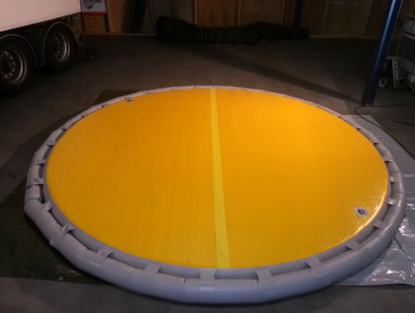
Picture 13 Inflatable internal floating roofs, iifr here in version of a (yellow) inner disc, made of a 3D elastomer material, rigid trough inflation, and a dedicated, separately inflatable circumference ring, the “bicycle tire” for optimal sealing
Improvements of iifr’s over other floating roofs
IIFR’s have the advantage of being removable because of their in- en hence deflatable design and construction. This allows for their removal from the tank in case of maintenance or inspection when workers may have to enter the tank. By removing the iifr, the tank can be degassed as one entity improving the safety features considerable over permanently fixed shaped internal roofs. The iifr’s thereby eliminate the “confined spaces” problems of other internal roofs, as mentioned above.
IIFR’s do not (have to) land on legs when a tank is emptied which avoids vaporization and emissions. IIFR’s can land on the floor of the tank, especially when in- and outflow hose provisions are used and other tank internals are “cage”-protected.
IIFR’s are transferred into tanks as one complete product (without any joints) and do not require any manual assisted work inside the tank to make these operational, unlike all other type of internal roofs.
IIFR’s air (nitrogen), hence energy, consumption is very little and require virtually no control nor operator assistance. The operational complexity is far less as compared to the energy consumption and cost of vapor recovery units.
IIFR’s cannot and do not sink.
Further improvements
While the inflatable internal floating roofs provide for many advantages of other (non-inflatable) internal roofs, they still result in an enclosed space between the two roofs which remains undesirable as this space may, will, (very slowly) become vapour filled with resulting emission consequences.
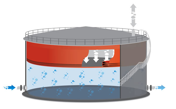
Figure 14, schematic of a “full volume” inflatable roof.
To eliminate such space between two roofs one may use a “full volume” inflatable roof, as shown in the above picture as the orange device inside the tank, fills up all that space inside the tank which is not taken by the liquid containing all air which would otherwise be free inside the tank. The full volume roof is made as one prefabricated product of which the bottom or lower disc fully covers the liquid surface and of which the shell provides a seal over the entire tank shell height above the liquid level. The “full volume” inflatable roof requires to be an enclosure, for example to allow for a slight internal overpressure to force its side wall against the inner tank wall. The enclosure hence includes a roof or upper disc. This appears to be superfluous as the tank is also equipped with a fixed roof or eco-dome. And, one roof meets the requirement of “preventing things falling out of the sky into the tank, as detailed in the Introduction of this paper. So, let’s address:
Roof operations.
Quote [7]:
“Sudden Deaths Among Oil and Gas Extraction Workers Resulting from Oxygen Deficiency and Inhalation of Hydrocarbon Gases and Vapors — United States, January 2010–March 2015. Oil and gas extraction workers experience high rates of traumatic work-related fatalities. Tank gauging and sampling activities can expose workers to high concentrations of hydrocarbon gases and vapors (HGVs), in some cases at levels immediately dangerous to life or health.”
(Unquote)
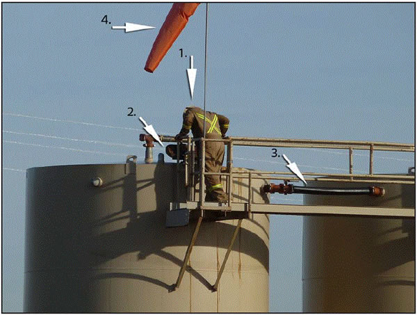
Picture 15, Unsafe sampling operations
Roof operations shall preferably be refrained from, especially while current metering, control and safeguarding technology allows to do so. The “add-on” of a stair should be re-evaluated. The option of storage tanks not being provided with stairs as there is no longer any need for human presence near, or especially on top of, the tank is the “best”, thus preferred.

The same concept design philosophy applies for example for (rim seal) fire-fighting equipment and for vapour recovery systems. Elimination of the risk of a fire and of vaporisation of the liquid shall be considered as “best”, thus preferred as target.
"CAIRBAG®" ROOFS
A "Cairbag®" roof consists of an enclosed and therefore inflatable element, the top of which forms a convex (round) roof when inflated, which is placed on an open top steel (or concrete) cylindrical tank. The bottom of this inflatable element is in full contact with the complete liquid surface at all times ensured by the (slight) internal over-pressure in the element. The top and bottom of the Cairbag roof are connected to each other by a cylindrical part to form the closed element. The cylindrical sidewall, shell is designed and constructed such that it allows the bottom to move along with the liquid level, while the top of the element remains form-retaining in its "roof" position.
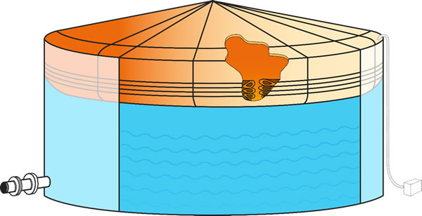
Figure 17 , schematic representation of a Cairbag roof.
The Cairbag roof is seized and dimensioned to fill the entire tank when it does not contain any liquid. The sum of the air volume in the Cairbag roof and the liquid volume in the tank always equal the fixed total tank volume. So, the more liquid there is present inside the tank, the less side wall material of the Cairbag roof will be operationally required. The minimum side wall seal height is equal to the tank height minus the high liquid level. Even at this minimum contact surface of sidewall and inner tank wall there is ample sealing.
The design and functionality of the Cairbag®" roof depend largely on the relevant folding and bending properties of the material chosen for this type of roof. Bending shall hereby be predictable and repetitive, while folding shall always be avoided. Furthermore, bending of the material is required to ensure the material to be pulled away from and to roll back against the inner tank wall and to avoid wear and tear.
The bending behaviour of the Cairbag roof material, when filling and emptying the tank shall by design always ensure such bends to be directly above the fixed shaped bottom of the roof. This bending materializes by design such that no side wall material gets “trapped” in bends, in which the bending behaviour possibly may become subject to hydrostatic pressure of the liquid. and thereby even may become “folds”. Such would result in side-wall material restricting the bottom of the Cairbag roof to descend or rise in accordance with the changes in liquid volume and level in the tank. Side wall material which is operationally not required to create the necessary volume of the Cairbag roof is accumulated in bends inside the roof on top of the bottom of the roof.
The internal overpressure (of a few millibars), the correct dimensioning of the Cairbag roof, and the correct accumulation management of material not used, ensure a good seal over the entire height over which the side wall of the Cairbag®" roof is pressed against the tank inside the side wall.
The thermoplastic or rubber material to be used to manufacture Cairbag roofs comprises a strong (PA or PU) virtually non-elastic carrier and relatively softer coating on both sides of the carrier. The relatively soft coating is pressed into every pore, pit, rub, etc. of the inner wall of the steel tank. The sheet material also adjusts in shape to any "radii of curvature" of the tank and local deviations therein. This sustains the quality of the seal.
The "Cairbag®" roof by design and construction, does not allow evaporation of the stored liquid, since there is no free air directly above, nor in contact with the liquid. This makes a tank with this type of roof emission-free.
Inflatable, inflated roofs do not sink.
A "Cairbag®" roof application results in a complete separation of stored flammable liquids and air and in the absence of any vapours. This is considered to be “best” in terms of mitigating fire and explosion risks. A "Cairbag®" roof may be filled with Nitrogen if such would be preferred for example for further fire and explosion risk reducing arguments.
The air (nitrogen), hence energy, consumption by a "Cairbag®" roof is very little and require virtually no control nor operator assistance as compared to vapor recovery units. The cost and environmental effectiveness of Cairbag roofs is significantly more attractive too.
The Cairbag roof technology is to a large extent already applied in agricultural and farm (mist storage) applications. See picture .
Picture 18, A Cairbag kind of roof for a mist collection tank at a farm. A small internal over-pressure is sufficient to support a man.
BEST AVAILABLE TECHNOLOGY
The question of “what is the best available technology?” is preceded by the four following questions:
- What technologies are available?
- When is a technology “available” or “proven” and when not?
- What technology is the best and why is such technology better than others?
- What determines the choice if more than one technology appears to be available?
The answers to these four questions will hereinafter be provided. The easiest to answer are the questions “What technologies are available?” and “What technology is the best and why is this technology better than others?”. This paper provides in its entirety the detailed answers hereto.
The remaining two questions require quality statements and definitions of the terms “best” (“better”) and of “available” (“proven”). Luckily, science, technology but also politics and legislation have encountered these questions before (especially on topics other than storage tanks) and answers are therefor available. The following three references are made thereto:
[1]. The “Qualification of New Technology, Recommended Practices” issued by: Det Norske Veritas.
[2]. The Technology Readiness Levels (TRL’s)
[3]. Official title: Law of 6 November 2008, containing rules on a licensing system with regard to activities that influence the physical living environment and on the enforcement of regulations in the field of the physical living environment
Also known as: Wabo in The Netherlands
The question of: “When is a technology “available” or “proven” and when not?”, can be answered starting with reference [2]. Following is quoted thereof:

Figure 19, Technical Readiness Level, TRL, representation
“ Technology readiness levels are a method for estimating the maturity of technologies. The use of TRLs enables consistent, uniform discussions of technical maturity across different types of technology. A technology's TRL is determined during a Technology Readiness Assessment (TRA) that examines program concepts, technology requirements, and demonstrated technology capabilities. TRLs are based on a scale from 1 to 9 with 9 being the most mature technology. The universal usage of TRL in EU policy was proposed in the final report of the first High Level Expert Group on Key Enabling Technologies, and it was indeed implemented in the subsequent EU framework program, called H2020, running from 2013 to 2020. This means not only space and weapons programs, but everything from nanotechnology to informatics and communication technology. “
As this paper highlights technologies have been developed and demonstrated (“TRL 6”) already for applications other than storage tanks. Such technologies will serve very well for the application engineering, system development for storage tanks. In view of the value of stocks held by storage tanks and the value of the tank terminal infrastructure, hence of the liabilities, it may be opportune to prepare for a submission of an “Approval In Principle” request, as per reference [1] for first applications.
The above provides the basis for the answer to the last (fourth) question: “What determines the choice” of technology to be used, if more than one appears to be available?. The answer of this question is determined by law, reference [3].
The definition of "Best Available Techniques" (BAT) can be found in the Wabo ([3]Article 1.1, paragraph 1), quote:
“The most effective techniques for achieving a high level of environmental protection to prevent emissions or other adverse environmental effects that an establishment may cause, or, if that is not possible, to be minimized, which - costs and benefits taken into account - economically and technically feasible in the industry to which the establishment belongs, that can be applied and that can reasonably be obtained by the person operating the establishment in the Netherlands or abroad; In this context, techniques also include the design of the device, the way in which it is built and maintained, as well as the method of operation and the way in which the device is decommissioned.”
Article 2.14 provides for the necessary clarity: quote:
“
1. Insofar as the application relates to an activity as referred to in Article 2.1, paragraph 1, under e:
c. the competent authority will in any case observe that decision:
1 °. that at least the best available techniques eligible for the establishment or the mining work must be applied in the establishment or the mining work.”
As can be read in the definition, the best available techniques are determined by both technical and economic opportunities for an industry and are to be applied by law. An Addendum to this paper was prepared to address the economic attractiveness of new “Best Available Technologies” and their applications.
Best Available Technologies, as specified in concept in this paper appear to comply with relevant and applicable international standards, including:
- EC/94/63, EU legislation on emissions of volatile gases and vapours, ref [4], PGS 29, ref [4],
- API 650, Appendix H, ref. [5].
- PGS 29 (The Netherlands), ref. [6].
Such legislation and standards generally do not prohibit the use of “new” best or better technologies but rather allow or even encourage the use of such.
Conclusion
The technologies applied in tanks currently used for the storage of liquids, including such qualified as “dangerous”, are not “the best”. There are clear trends identifying the need to improve the containment functionality of storage tanks. These trends are more prominently manifested by applying “double roofs” rather than “double hulls”. The rapidly increasing number of double roof applications confirm the importance of avoiding vaporisation and of avoiding the presence of vapours within tank constructions.
The sealing functionality of rim seals, as used with rigid floating roofs, is compromised, by design and construction, on the non-compatible wear and tear resistivity requirement. Tank designs and products should however be based on “not allowing any gap in between a roof and the inner tank wall”.
Better technologies like “Linerbag” and “Inflatable Internal Floating Roof” are available and of a Technical Readiness Level which is sufficient to consider these to be mandatory by current Laws (in the European Union). There is currently an obvious and significant “gap” between the technologies practically being applied and the best available technologies obligatory by law.
Note: A “green deal” proposal, by author, made in 2011, aiming at eliminating this gap, has become the request for Dutch government support with the longest non-response time.
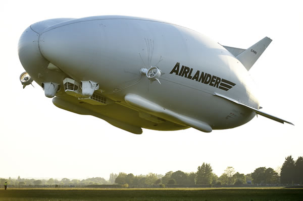
The new Cairbag roof technology is a next step in becoming the “Best Available Technology”. It should be encouraged both by tank owners, users and authorities to pursue the relatively easy “Approval In Principle” procedure of DNV, ref [1]. Such “AIP” approval and inherent confirmation of a sufficient TRL level have become “easy” for example in view of similar approvals having already been obtained for the “Airlander”, see picture 20, with the aviation-based approvals and for large stadium covering roofs (which collapse less frequently than steel made stadium structures).
FOOTNOTE (1)
Large volumes of liquid are not only stored in steel tanks. The question here is: “Is the use of steel for the bottom and shell as part of a bulk liquid containment facility the best available technology?”. In that context, a wider perspective of trends and developments with a possible impact on Best Available Technologies for bulk liquid storage is considered essential. This footnote hence addresses two items thereto.
Caverns.
Although large volumes of liquids are already being stored in caverns, there remain concerns over how good such storage is.
Such concerns are mostly related to the integrity of the cavern wall, the risk of groundwater pollution, the lack of inspection and repair possibilities, the complex procedures of handling calamities. New technologies, as described in this paper, may also be applied in caverns to improve on current technologies
Multi-layered infrastructures build of concrete.
Multi-layered man-made infrastructures, especially port facilities, is a new field of developments which is especially interesting for very intense economies in densely populated, often relatively small land surface areas. New technologies in this specific field are characterised by:
- no steel is applied in the bulk liquid storage facilities,
- the application of the “clean room principle”, with the absence of any air in the surroundings of the stored liquid. Such surroundings are generally water and nitrogen filled.,
- The high level of controllability and safeguarding,
- The high flexibility and operational simplicity of changing the infrastructure to allow for the storage of products different to such prior being stored.
- The reduction of exposure against acts of war and terrorism.
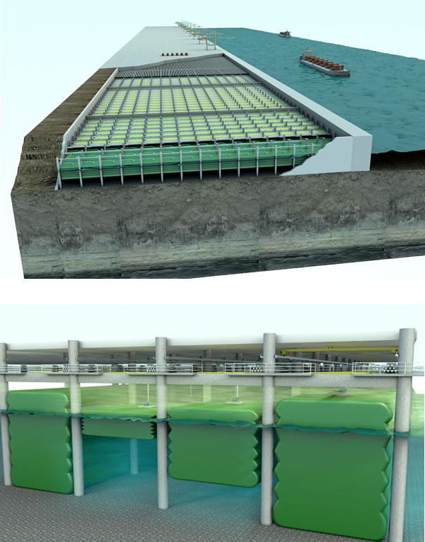
Figure 21 (top) and (bottom), Impressions of multi-layered infrastructures
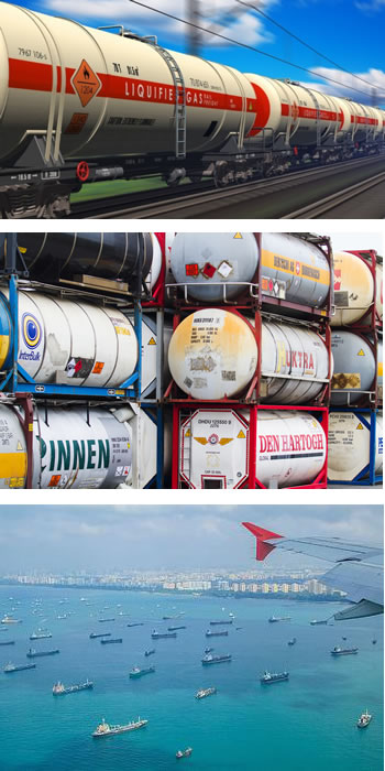
Mobile tanks
Mobile tanks are increasingly used in a long-term stationary position to provide “temporary” liquid storage facilities. See pictures 22. This is beyond doubt done for economic reasons. In many cases, it remains questionable whether this meets the locally applicable laws, regulations and permits as would be applicable for permanently installed (steel) storage tanks.
Acknowledgements
Centre for Industrial Safety, “Dangers of tanks with a fixed roof and split-welds, ref [8].
Tebodin, Environmental Impact assessment of an extension of the Maasvlakte Oil Terminal. Ref [9].
Accede b.v. Intellectual Property Base.
Accede b.v. registered Trade Names.
Accede b.v., The “Technical Development and Deployment Release” document as prepared for Shell.
REFERENCES
[1]. The “Qualification of New Technology, Recommended Practices” issued by: Det Norske Veritas with reference DNV-RP-A203, July 2011
[2]. Technology Readiness Levels (TRL’s); Source: Wikipedia, last checked: 30 August 2019.
[3]. Official title: Law of 6 November 2008, containing rules on a licensing system with regard to activities that influence the physical living environment and on the enforcement of regulations in the field of the physical living environment
Quote title: General Provisions on Environmental Law
Also known as: Wabo, The Netherlands.
[4]. EC/94/63
[5]. API 650, Appendix H
[6]. PGS 29
[7].
8]. Centrum Industriële Veiligheid, “Gevaren bij tanks met een vast dak en scheurnaad”, IV Alert 17-01
[9]. Tebodin, Samenvatting Milieueffectrapportage uitbreiding opslagcapaciteit Maasvlakte Olie Terminal, 31 Maart 2008
[10] BRL K-21017, Kiwa
Footnote (2):
This paper presents the “Technical scientific” version of the topic. This paper is intended to possibly serve as a “basis for innovative conceptual design for liquid holding tanks”.
You may also wish to obtain the addendums on:
- Cost effective and economical perspectives, or the
- Implementation or application engineering and remaining scope for further research.
- Political and law enforcement aspects.
Reference of this document: Acc19071, Revision 0.2 of 26 December 2019.

Picture 23. “If I had asked my customers what they wanted, they would have said, the same tank but cheaper and quicker