Interfaces between tanks and Cairbags.
Erik Jeroen Eenkhoorn
PhD, MSc, MBA
Hengelo (O), The Netherlands
ABSTRACT
Load securing of liquids in mobile tanks impacts on the core of the bulk liquid transportation world. The use of an inflatable and inflated component hereto, as a “Cairbag” system does, results in “new hardware” to be in direct contact with the liquid, the tank and possibly with all its provisions including such applied for the safeguarding of the tank. Equally elementary is the impact of liquid load securing on the physics, and changes therein, to which the mobile tank and the means of transportation it is or can be part of, are subjected during liquid transportation. The success of securing liquid loads and benefitting from the advantages thereof depend largely on the professional engineering of all interfaces between Cairbags and key transportation elements. This paper addresses these interfaces and provides engineering details thereto.
KEY WORDS
Cairbag; inflatable component; mobile tanks; interfaces; cleaning; liquid transportation; over-pressure; over-filling, liquid load securing, means of transportation,
INTRODUCTION
A Cairbag application results firstly in an interface with the liquid in accordance with the intended advantages to be gained by, and justification for its application. Secondly, A Cairbag has an interface with the air filling such space inside the mobile tank not taken by the liquid to be transported. Furthermore, the application of a Cairbag inside a mobile tank results both in direct interfaces between the Cairbag and the tank containing the liquid to be transported as well as indirect interfaces with the means of transportation. The interfaces between a Cairbag and a mobile tank, and between a Cairbag and the means of transportation, will be the focus of this paper. The interfaces of Cairbags with the liquid and air content of a mobile tank will firstly be summarized for completeness of the total “Cairbag interfaces” overview.
INTERFACES BETWEEN THE CONTENT OF A MOBILE TANK AND AN INFLATABLE COMPONENT BASED CAIRBAG SYSTEM
The most prominent interface between a liquid to be transported inside, and partially filling, a mobile tank which is provided with a Cairbag is the prevention of any dynamic movement of such liquid relatively to the tank. The Cairbag secures the liquid cargo in accordance with the functional aim of its application. Refer [1]. The Cairbag, especially the variable volume type, will cause a (slight) increase in the back-pressure encountered by the liquid during the loading process of the tank.
Furthermore, a variable volume Cairbag system does not allow for any free air inside the tank at any point in the transportation cycle. This has following consequences:
- The liquid cannot evaporate and cannot chemically react with air,
- No water possibly condensing from the air can migrate into the liquid,
- No other substances in the air, like insects, can affect the liquid quality,
- The liquid quality is maintained better due to the above,
- The fire and explosion risks are reduced due to the separation of liquid and air,
- The air remains “clean”, the tank hence does not cause emissions.
Vapour return
Highlighted is the fact that the Cairbag does not allow for “return vapours” to be positioned “free” inside the tank, i.e. filling such space as became available by the liquid being off-loaded from the tank. The Cairbag may be filled with such return vapours but this is not advised. Vapours may for example condensate causing the Cairbag to be (partially) liquid filled with the possibility of liquids accumulating over multiple cargoes in time. The ownership and related liabilities of “returned vapours” being passed-on in the transportation chain is another source of concern. The transfer of vapours in the transportation chain is strongly opposed to, one should hence aim at preventing vaporization in every link of this chain.
Additionally, there is the interface on “cleaning aspects” of the mobile tank in relation to the liquid held in it and the consequences of the presence of air or not. Refer [2].
STRUCTURAL INTERFACES BETWEEN A MOBILE TANK AND AN INFLATABLE COMPONENT BASED CAIRBAG SYSTEM.
Dedicated Tank-wall Passage Provision
A Cairbag system may require, include a passage provision in the mobile tank wall to allow air or other inflation gas to be transferred into or out of the inflatable component. Such passage provision, if applied, also caters for the transfer of pressure data from Cairbag components inside to those outside the mobile tank. Cairbags of the variable volume type generally include such tank wall passage provision. Those of the fixed volume type generally not.
In case a tank-wall passage is part of a new to be applied Cairbag system one generally prefers to use an existing, blinded-off (flanged) opening or provision available on top of the mobile tank. This avoids having to modify and thereby having to pressure test and re-certify the tank. A new to-be-build mobile tank is preferably provided with a 6” (DIN 150) dedicated flange connection on top of the tank.
The manhole (cover) may be provided with a provision to hold the pneumatic hose-end and valve of a fixed volume Cairbag system (without permanently connected provisions externally of the tank). This provision may be a kind of a “hook and eye” type.
The Manhole Opening and Manhole Cover
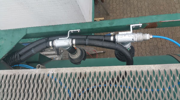
The manhole provision including its cover, when in the “opened” position, allow for a “top-fill” of the tank. The presence of a Cairbag does no longer allow for the possibility of opening the manhole and inserting a fill-pipe to bring liquid, by “free-fall” into the tank. In case a top-fill is required, dedicated liquid entry connections and tank wall passage must be provided at the top of the tank. The liquid then also requires to be routed via hoses running vertically internally along the inner wall of the tank and ending at a position which is always below the lowest position the Cairbag can be at, see figures 1 and 2 for an example of such provisions.
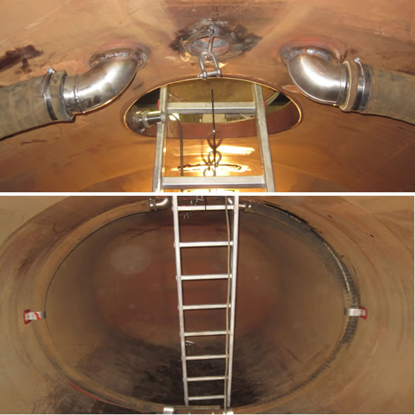
Figures 1 (top) and 2 (bottom): The water supply in the tank. The center is the old connection, where a suspension has been made for the inflatable component. The water supply is guided to the bottom of the tank by means of two reinforced hoses. These are connected to the inner tank wall.
The manhole is often routinely opened to avoid a pressure build-up in the tank during liquid loading or to avoid creating a vacuum in the tank during liquid off-loading. An opened manhole allows for visual monitoring by the driver and, or the load master, of the fill level of the tank. A Cairbag application terminates these possibilities!
For safety, health and emission avoidance reasons, the manhole has always to remained closed with the only exception when required for Cairbag dedicated cleaning, refer [2] and for access for inspectors or inspection equipment if such is required for inspection purposes. The safety aspects relate to the inflatable component of a Cairbag system possibly obstructing and sealing off the entire manhole opening, especially during the (final stage of the) liquid fill process. The inflated component may thereby not allow for any air passage, or for too little air-passage to avoid an over-pressure or vacuum situation in the tank. A (mobile) tank shall always be designed and constructed with a normal operations air in- and outlet and be designed and constructed with separate dedicated over-pressure and vacuum safeguarding provisions.
The inflatable components of a Cairbag system by general definition, fill all space inside a tank not taken by the liquid cargo. They thus make the tank emission free as there is no free air inside the tank in which the liquid could or can evaporate. The tank thereto has always to remain closed. The manhole is not to be opened neither is there any vapour return connection to be opened.
The tank remaining closed, also during (off-)loading requires engineering and a proper risk assessment of every possible over-pressure, vacuum or (under-)pressure condition and of the tank overfill protection. This has resulted in following details thereto.
The liquid outflow of the tank
The liquid outflow of the tank may be protected such that Cairbag material cannot be “sucked” into the outflow during (final) liquid discharge operations. See figure 3. The provision is not necessary in case of a fixed volume inflated component as this component will remain positioned in the upper part of the tank during liquid discharge, hence will not come anywhere near the liquid outflow point. The necessity of such provision is also questionable as the material of the Cairbag will only reach the liquid outflow point from the tank at the final liquid discharge stages when the Cairbag is fully inflated. At this point there is no spare “flabby”’ Cairbag material available to be pulled into the outflow opening. The outflow securing provision may be required in case of applying cleaning operations requiring the Cairbag to be deflated and to be positioned at the lowest point inside the tank, refer [2].
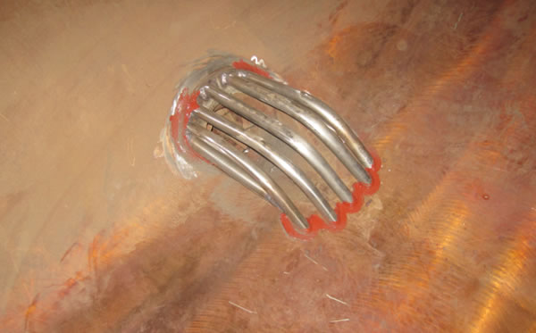
Figure 3. An example of protection of Cairbag material being pulled into the liquid outflow opening of the tank. Other, non-welded to the tank, type of provisions, if required, will be more practical.
Liquid outflow openings of “ADR” tanks, mandatorily provided with an internal shut-off valve, shall always be examined on the interface risks of Cairbag material affecting the functionality of the valve. This may result in the requirement to apply a safeguarding securing provision of such internal tank valve.
Baffles
Baffles become obsolete in case liquid cargoes are secured. Baffles aim at mitigation of the sloshing of liquids in the driving direction of a mobile tank. If liquids are secured, they do not slosh anymore (in any direction), hence the obsoleteness of baffles.
Baffles preferably are not applied as this results in a considerable net weight saving and in a capital cost saving of the mobile tank.
There are two key aspects:
- Baffles, when used, result in extra requirements for manholes, as access to each tank section is mandatory, extra in-and outflow and extra safeguarding provisions. Baffles, when used, result in some tank strengthening not to be required, which strengthening would be required in case there are no baffles applied. A Cairbag application for liquid load securing and tank strengthening provisions weight and cost (far) less than baffles and related extra tank provisions.
- The use of baffles in partially filled mobile tank is mandatory by law in case the liquids are qualified as “dangerous”. Refer [3].
Note: The topic of liquid load securing and the acceptability of using Cairbags rather than baffles is currently still subject to official UNECE “Tank Work Group” (and working party 15) endorsement.
SAFEGUARDING INTERFACES BETWEEN A MOBILE TANK AND AN INFLATABLE COMPONENT BASED CAIRBAG SYSTEM
The safeguarding aspects of the interface between mobile tanks and Cairbag applications are the most serious of all interface aspects.
Firstly, an inflated component of a Cairbag system may not cause any risk of blocking or limiting the access of air, liquid or vapours remaining inside the tank at a pressure higher than the high-pressure safeguarding set-value of the PV-valve of the tank. This equally applies for the inflow of air into the tank in a Vacuum, or under-pressure situation.
Secondly, an inflated component of a Cairbag system may not cause any risk of overfilling the tank (with liquid) as the inflated component eliminates the possibilities of direct human visual control over the fill level of the tank. Insufficient filling of a tank provided with a fixed volume Cairbag is also to be avoided.
Both the pressure and the volume fill-rate related aspects will be analyzed hereinafter especially in relation to current mobile tank design and construction details thereto.
A Cairbag application in general improves the safeguarding of a mobile tank. A Cairbag system itself includes pressure and pressure safeguarding design features and provisions in addition to those of the tank. So, provided the tank safeguarding is not affected by the Cairbag system, the Cairbag provides for an increase in safeguarding provisions.
Furthermore, mobile tanks are currently not designed nor constructed to withstand locally, short duration peak pressures resulting from liquid dynamics. Although the tank main (metal) body is not affected by such short duration peak pressures, provisions like manhole covers and pressure safety valves. Even though such peak pressures may seldom occur during normal transportation conditions, they should be a concern in case a mobile tank is involved in an accident.
The ADR [3] recognizes and thereby confirms such in ADR Article 4.2.5.3 and the special provision "TP24" for the transportation of hydrogen peroxide (with UN number 2014 or 2015). This article requires the use of a "device that must prevent the escape of an inadmissible amount of fluid or the ingress of foreign matter, even when the tank tips over". A "Cairbag" and especially its inflated component perfectly matches the requirements of this article. The Cairbag forms a nice buffer in between the liquid and the manhole (cover) in case of a mobile tank keeling-over accident, accumulating the impact energy and mitigating the dynamic pressure impact on the cover.
The surface of a manhole cover generally is so large that it can accommodate a short duration peak pressure on a much smaller part of its surface without serious consequences. This is different for over-pressure protection devices. These are likely to open very briefly occasionally during normal driving conditions of the mobile tank. Consequences can however become adverse in accident situations. Reference is made to the LPG road tanker accident near Bologna, refer [4].
There two relevant aspects of this accident to highlight:
- The immediate failure of the fuel (diesel) tank of the tank truck and the inherent fire commencing.
Fuel tanks of all trucks, including tank trucks, are designed and constructed as “single hull”, with the least weight and positioned without any protection allowing for easy access in case of an accident. This feature causes (far too) often a fire in case of an accident involving a truck and causes thereby aggravation of the seriousness of the accident. This can easily be overcome by using a “bag” inside the tank holding the fuel and thereby making the tank “double hull”. Such bags are to be made of a thermoplastic, fuel compatible strong, elastic material with high tear resistivity. Such bags (for anti-theft of fuel purposes) have been tested and proved to be very effective in their containment capacity and to cost little. - The failure of over-pressure safeguarding provisions on the top of the mobile tank. The liquid dynamics in case of an immediate stand-still of a tank truck like in case of a head-tail accident will cause pressure peaks which may occur at the position of the high-pressure safety valve, often positioned near the front of the mobile tank. The pressure may, for a brief but sufficiently long moment, be higher than the valve set pressure or the maximum working pressure of the cover. Once any such device provides for an opening, vapours will progress from the tank into the external fire. The over-pressure safeguarding device is damaged in the process and therefore can and will not “close” again. This usually explains the fire to continue even long after the fuel, of the fuel tank initiating the fire, has gone. The prolonged fire lead to the catastrophic BLEVE killing one and injuring 145 persons in the Bologna accident case.
A Cairbag application prevents direct access of pressure peaks in liquids to the to be lifted disc of an over-pressure safeguarding device. This is done in a manner which does ensure the unrestricted access for such quantities of air, liquid or vapours thereof in over-pressure situations, see below.
Over-pressure and Vacuum Provisions
The tank remains to be protected against over- and under-pressure situations by the mandatory pressure safeguarding devices, i.e. the pressure valve (“PV”) commonly installed on top of the tank. The opening in the tank wall, accommodating the externally placed PV device, is provided internally with a T-connection. One side of this T remains open to accommodate for over- or under pressures in the top section of the tank. The other side of this T-piece is connected to a hose or tubing, which hose or tubing ends at the liquid in- and outflow provision at the rear and lower section of the tank. The hose or tubing is mounted on to the protection of the corrugated liquid in- and outflow cover inside the tank protecting the inflatable component from being sucked into the outflow device. This hose or tubing provision and its connection at the T-piece provides for direct access to the PV device thereby safeguarding the space underneath the inflatable component against over- and, or under-pressure. See also schematic “4”.
The two pneumatic sub-systems of the inflatable component have a dedicated and shared air pump supplying air to both the main chamber and the channels. The pump maximum pressure, as used in this case, is only 115 millibar thus limiting any risk of over-pressurizing of tank or inflatable component. Deflation of both the main chamber and the air channels during liquid filling of the tank is ensured by the two dedicated spring-operated relief valves. The main chamber is furthermore provided with a PV valve, serving as a further safeguard of both the inflatable component as well as the tank against over- or under-pressure.
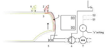
Schematic 4. Over-pressure safeguarding relief valve (nr.2) and T-provision (nr. 3) with hose to reach into liquid (nr 1) to mitigate risk of over- or under-pressure underneath the inflatable component and for the expulsion of free air being supplied as part of the operational liquid fill requirements. Electronic flow rate metering (nr 6) and external volume loaded metering (nr 7) is also shown as an over-fill protection means. The cairbag own pressure safeguarding is shown as nr 4.
Overfill Protection
The Inflatable component system and the inherent absence of any free air in the tank outside the inflatable component do not allow for traditional overfill protection devices to be used. These devices generally require a “dry” stage during loading, allowing for liquid to be pumped into the tank while they create an “inlet valve closure or pump stop” signal once the device “gets wet”. The main chamber of the inflatable component system operates at 20 millibar thus always causing a hydrostatic pressure in the liquid of 20 millibar more than would have been the case when no inflatable component is used. The liquid static over-pressure due to the inflatable component is subject to the air supply valve set pressures for opening and closing and the operating range thereof. These pressures range generally between 15 and 25 millibar. This range in pressures does not allow for an accurate switch point between “dry” and “wet” conditions, hence cannot be used for a traditional overfill protection system. The range in liquid fill levels, at which the overfill device could see liquid, is furthermore too large to be acceptable in both safety and economical terms.
In view of the traditional overfill protection devices not being usable when an inflatable component is applied, the functionality and design of the inflatable component system was expanded to include and assure liquid overfill protection.
The two air sub-systems and the design of the inflatable component result in the following sequence of events during liquid filling of the tank. Firstly, the main chamber continuously blows of air via the dedicated relief valve controlling the maximum pressure in the main chamber at 33 millibar. The pressure in the main chamber remains therefor constant over a large part of the 0 to 98% range of liquid fill levels of the tank. Secondly the air channels (2%) remain to be filled with a same quantity of air during the liquid fill process of the tank. No air is added to these channels as the channels were filled to maximum volume at a working pressure of some 45 millibar when the tank was empty (i.e. 100% Inflatable component filled). While the tank is filled with liquid and the main chamber of the inflatable component reduces simultaneously in volume, the circumferential air-channel(s), enabling the transfer of air to and from the longitude channels, reduce(s) in volume. The inflatable component progresses to be positioned in the top of the tank during its deflation process, remaining afloat on top of the liquid. As the pressure relief valve of the air channels is set at 65 millibar. The constant air quantity continues to be compressed in the diminishing volume of the air channels. While the pressure initially only marginally increases (1 millibar over first 50% liquid volume fill), the pressure increases much quicker above a 95% liquid fill rate of the tank.
Picture 5: Overfill protection test of the truck (on the left) provided with an inflatable component system and a water buffer truck (on the right).
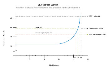
Figure 6: Graphic presentation of the relationship between the liquid volume fill level of the tank and the pressure in the air channels of the inflatable component system.
This repetitive feature is used both to provide for the “near full” operational warning as for the “liquid fill pump” automatic switch off at 98% liquid fill level. The tank truck early warning and liquid pump switch off signals are in addition to the normal and safeguarding liquid loading operations of the liquid producing facilities. The warning at 95% fill level allows the operator, truck driver to switch off the liquid supply pump(s) manually and to close relevant valves while still being able to pump the liquids, possibly still being present in the interconnecting piping and hoses between tank truck and production facilities, into the tank of the truck without exceeding the maximum allowed fill level of the truck.
Volume Fill Level
Traditional Metering using the “dip stick” to determine the height of the liquid level in a tank cannot be used. Such dip sticking requires an opening of the tank which consequently results in vapours escaping from the tank causing emissions.
Dip sticking is also not possible when inflatable components of Inflatable component systems are positioned over the liquid in a tank.
The use of other common level instruments like displacement level gauges are radar-based level metering is equally impossible or likely highly inaccurate. The folding of inflatable component material being spare in less than 100% volume fill of such component and thus the absence of a flat horizontal liquid surface and the inflatable component material not being single layered at every point of liquid contact, are the prime causes of such inaccuracy.
The volume of the liquid loaded in a tank must be determined by using flow-metering, outside the tank. Such flow-metering is commonly available in view of the custody transfer taking place when liquids are pumped from a storage facility into a means of transportation. Flow-meters may even be present both at the liquid storage and loading facilities site as well as on the truck loading the liquid. The metering facilities, and, or their IT support shall allow for aggregation of flow data to provide for accurate data on the actual liquid volume loaded into the tank. An automatic reset to “0” upon every discharge after which the tank is without liquids (“empty”) is recommended.
INTERFACES BETWEEN MEANS OF TRANSPORTATION AND AN INFLATABLE COMPONENT BASED CAIRBAG SYSTEM.
Picture 7: Several components, externally of the tank, like the air or inflation gas blow-off valves as can be seen in the picture, are to be positioned and mounted on the means of transportation.
Forces and Energy; Braking and Accelerating.
The first interface between a means of transportation and an inflatable component based Cairbag system are the changes in forces exercised by the liquid dynamics on the mobile tank and subsequently on the means of transportation to the point where such forces are compensated by (equal) reaction forces and where the energy is absorbed. The changes also apply to the transfer of energy between the means of transportation and the liquid (via the mobile tank) and vice versa. A Cairbag application results in such forces and energy transfers to change far less erratically and to be of less magnitude in comparison with a mobile tank without such Cairbag application. This affects the “chassis” of the means of transportation, i.e. the structural parts from the tank supports to the tires and all moving parts between engine and brake, and the tires. The results of a Cairbag application include:
A reduction of the wear and tear of many components of the means of transportation, like the transmission, the gear box, etc.
A reduction of the fuel consumption of the means of transportation.
Possibilities to reduce the net weight of the means of transportation.
And likely even more important:
- The improvement of the controllability of the braking process by the truck driver, especially as the kinetic energy of both the means of transportation and the liquid cargo is all absorbed by the brakes where deceleration of all liquid is identical as such of the means of transportation.
- The increase in energy to be absorbed by the brakes as all kinetic energy of the liquid will be transferred to the brakes in case of braking of the means of transportation.
- The reduction in the fuel consumption as there are “sloshing” losses.
Electronic Stability Control and Anti-Lock Brake Systems
The second interface between a means of transportation and an inflatable component based Cairbag system relates to the various new “add-on’s” which have been introduced to means of transportation comprising a mobile tank, especially tank-trucks.
These introduction and wide implementation of means to increase the stability against adverse effects of sloshing of the means of transportation, confirms the stability concerns in the bulk liquid transportation industry. Various new “Electronic Stability Control”, ESC systems and Anti-Lock Brake Systems (ABS) have been made available and are commonly a “standard” provision on means of bulk liquid transportation.
New electronic technology systems, like the ESC, focus on responding reactively to events happening inside the tank rather than pro-actively eliminating (the cause of) such events. An example of such reactive approach is: allowing LNG to boil-off and then recompress the vapours. Less cumbersome is to anticipate and adopt a pro-active approach of avoiding the boil-off thereby not having to re-compress gasses or vapours.
Electronic, roll-over, stability systems do not have any direct interface with the liquid or the sloshing thereof and were therefore not further explored.
Slosh impact on ABS supported braking
Longitudinal sloshing of liquids causes the loading of the axles to vary. When during braking of a tank truck the liquid load is positioned over the rear axles, the ABS will apply the highest braking moment on each of the usually three rear axles. When the liquid load starts moving forward in the braking process and the loading of each rear axle reduces, the ABS proactively reduces the braking momentum on these rear axles to avoid the wheels starting to slip. The ABS subsequently only, reactively, allows for and commences to increase the braking moment on the, usually one, driven axle supporting the front of the tank. This, however, only happens after the liquid has arrived in front of the tank, and the loading of the driven axle consequently has increased. The ABS system thus reduces the overall brake moments being applied on the wheels of the mobile tank supporting axles, as compared to constantly loaded axles. This ABS characteristic increases the braking distance by several meters, subject to the response quality of the ABS system (in terms of frequency, speed and level of response to changes in loading of the different axles). The ABS system furthermore has no effect on liquid sloshing as from the moment the truck (tank) comes to a stand-still. See also figure 8.
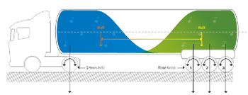
Figure 8. A schematic representation of a half liquid filled mobile tank of a truck with 3 rear axles and 1 driven front axle. The center of gravity of the liquid moving, during braking, often in between the “green” and the “blue” positions, i.e. “sloshes”. This affects the gravity force, load on each axle with the ABS adjusted braking moment accordingly.
Springs and Dampers
Springs and Dampers of the means of transportation will be exposed less to severe conditions in case of a Cairbag application.
Conclusion
The impact of a Cairbag application on the safe transportation of bulk liquids is intense as it has interfaces with virtually every detail of the key elements of such transportation. Professional engineering is a minimum requirements to ensure the success of such Cairbag application. The multiple Cairbag varieties, each being optimized for their application specific targets, result in application-based engineering. There is no “one solution fits all”, various applications will however have a high level of repeatativeness.
Acknowledgements
TÜV Nord “ADR” and “Food” Certification of Cairbag load securing systems.
Feldbinder tank-truck builders for their interest in investigating the attractiveness of a “Cairbag” optimized mobile tank.
REFERENCES
[1] Eenkhoorn, E.J. (2017). Products to mitigate liquid sloshing, University of Twente, Enschede, The Netherlands. ISBN 978-94-6233-808-1
[2] Eenkhoorn, EJ (2018), “Cleaning of tanks and Cairbags”.
[3] United Nations Economic Commission for Europe, European Agreement concerning the International Carriage of Dangerous Goods by Road (“ADR”), Geneva, 30 September 1957.
[4] https://youtu.be/fWY7jqQvfJU . You tube: film on LPG road tanker accident near Bologna August 2018