
Proceedings of 8th Transport Research Arena TRA 2020, April 27-30, 2020, Helsinki, Finland
Don’t be sloshed, don’t be baffled, secure your liquid load.
Erik Eenkhoorn PhD
aAccede b.v. Smutsstraat 26 b, 7551 HM Hengelo (Ov.) The Netherlands
Abstract
Bulk liquid cargoes which only partially fill a mobile tank, slosh during their transportation. This sloshing has a detrimental effect on the stability and thus on the behaviour of the means of transportation. The consequences of such adverse effects include not only safety aspects but also environmental and economic aspects. Until recently, one was unaware of the importance of, and of the many improvements that could be made by securing liquid cargoes. Research, recently completed at the University of Twente, The Netherlands, not only confirmed the magnitude of the adversity of sloshing liquids, but also provided for bulk liquid slosh mitigating and securing solutions and new products thereto. (Eenkhoorn E.J., 2017).
Simultaneously, it was demonstrated that anti-slosh devices, in particular "baffles" as are currently mandatory by the "ADR" law, do not provide lateral stability and furthermore, significantly, but unnecessarily, increase the fuel consumption of the means of transportation.
Keywords: Slosh mitigation, tank/truck stability, liquid load securing.
Nomenclature
"ADR" is used as an abbreviation for the "European Convention on the International Carriage of Dangerous Goods by Road", which was established by the United Nations Economic Commission as for Europe (Geneva, September 30, 1957). Note: And as of April 2019, the ADR will no longer be restricted "Europe” but will officially be applicable worldwide.
1 Introduction
In this paper, the positive effects of mitigating the turbulent behavior of liquids in mobile tanks e.g. like tanks as used in tank trucks and tank containers will be addressed in relation to road safety. Turbulent liquid behaviour, also called "swapping" or "sloshing", is avoided by (correct) securing of the liquid which (of course) should be ensured before the beginning of the transportation. Firstly, the details of the design as well as of the basic principles of the technique of load securing products are detailed. The design of these liquid load securing products always includes an inflatable component, which is positioned inside the mobile tank. The improvements in stability and hence in safety achieved through the application of these liquid load securing products are quantified in terms of their impact on the brake distance of mobile tanks and the maximum speed with which mobile tanks can drive through bends. The privately funded and privately conducted research was initiated by concerns raised over the effectiveness of the mandatory baffle plates, the lack of attention for liquid load securing opportunities and the "static only" mandatory prescribed stability requirements. The remarkable promotion results of the research have already considerably improved the awareness in the society of the consequences on the road safety of not securing bulk fluids during their transportation. Actions to correct the (“ADR”) legislation are foreseen while the permission to apply means of liquid load securing in tank-trucks, for environmental improvements, has been obtained in the Netherlands and is imminent in Germany.
2. Means for securing liquid that partially fill a mobile tank
There are two principally different design alternatives for slosh mitigation products in horizontal cylinder-shaped mobile tanks as used in tank-trucks and tank-containers. These two varieties of liquid load securing products, with also reference to www.accede.nl, (explanatory film in the "homepage"), are based on using either:
Fixed volume inflatable components, or
Variable volume inflatable components.
Inflatable components generally are made of materials with a high Young’s modulus and thereby provide for hardly any elastic behaviour. The relatively high strength of the material allows for inflation of a component, of the fixed volume variety, to an internal pressure which is always more than the (external) pressure occurring in the liquid due to ac-, deceleration or resulting from driving through bends. The inflatable component therefor complies with the requirement of retaining its shape, dimensions and thus of its volume in all circumstances. The enclosed position between the inner tank wall and the virtually non-compressible liquid also ensures the component to transfer all occurring loads between liquid and mobile tank. The material of a variable volume inflatable component is sufficiently stretched and strained in the liquid (off-)loading process to accommodate relatively small pressure, i.e. stress changes due to ac-, deceleration or resulting from driving through bends. Important to note is that securing of any liquid cargo with an inflated component is done prior to transportation while nothing is done during transportation, identically to any other form of (mandatory) load securing for non-bulk-liquid cargoes.
2.1. Inflatable components with a fixed volume
Horizontal cylinder-shaped tanks, as used in tank trucks and tank-containers, can be provided with cylinder-shaped inflatable components. The length of the component is the same as the length of the mobile tank it is to be applied in. The diameter of a fixed volume inflated component is smaller than the tank diameter and subject to the required “pay-load” volume reduction of the tank. The fixed volume inflatable component may for example be used in cases whereby filling the tank 100% with liquid would result in exceeding the maximum legally allowed total weight (on the road) of the means of transportation and cargo. This is particularly the case with 20’ tank-containers, which commonly are designed and constructed to provide for the maximum possible volume within their dimensional constraints, when being used for the transportation of liquids with higher specific gravities. The fixed volume component, when inflated, reduces the pay-load volume of the mobile tank thus reducing the “free space” remaining to be available for liquid. The maximum legally allowed weight will thus not be exceeded when the remaining “free space” inside the tank is completely filled with a liquid of higher specific gravity. The liquid is simultaneously secured and cannot slosh, as there is no “free space”, thus improving the stability of the means of transportation. When the component is deflated or removed from the mobile tank, liquids of lower specific gravities can be transported with a volume equal to the full (or maximum) tank volume. The legally allowed maximum total weight of means of (road) transportation and cargo may also vary from one country to the next, especially like within the European Union. This fact also justifies the use of fixed volume inflatable components and inflate these in the country with the lower legally allowed maximum weight. Fixed volume inflatable components are generally used in mobile tanks for the shipping of complete liquid cargoes from “A” to “B” without intermediate (off-) loading of part of the cargo.
2.1.1 Principle of functional operation
The principle of the functional operation is firstly that the constant pressure in the inflated solid volume component is always higher than the pressure that exists in the fluid or that can occur (for a short duration). The second principle is that the upward pressure the fluid exerts on the inflated fixed volume component makes the transfer of high frictional force possible between the component and the inner tank wall. No relative movements between these two can or will occur hereby.
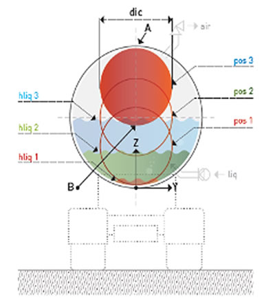
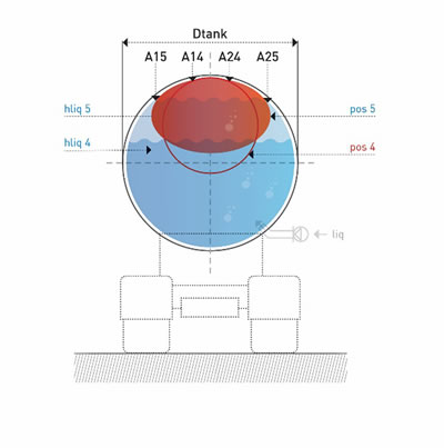
Figure 1. (a) and (b) Cross-section of a horizontal cylindrical tank containing an inflated solid-volume component showing the position and form changes during the liquid filling of the tank.
2.1.2 Functional working method
During loading of the tank with liquid, a non-fixated version of the inflated component will remain floating in the upper surface of the liquid. Figure 1. (a) shows a cross-section of a horizontal cylindrical tank containing a fixed volume inflated component that rises from position "1" to position "2" to position "3" when filling the tank with a liquid. In this last position there is a first (line) contact "A" of the component with the inner wall of the tank. The liquid height "hliq" is measured from the lowest point of the tank (z = 0). Figure 1. (b) shows the increasing compression of the inflatable component when the fluid level is further raised to position "4", with the contact surface of the inner wall extending between "A14" and "A24". Finally, position "5" is reached, in which the volume of the inflatable component and the volume of the liquid are equal to the volume of the tank. The contact area now extends from "A15" to "A25". The submerging of the inflatable component commences beyond the liquid level 3 at which point the upward force on the component and the capability of the component to transfer forces increases.
2.1.3. Basic formulas
A cylindrical inflated component shall have a length "Lic" corresponding to the length "Ltank" of the tank in which it is (to be) positioned and must have a diameter "dic" smaller than the tank diameter "Dtank" resulting in a volume "Vic", when inflated, which is smaller than the tank volume "Vtank". The difference between these two volumes is equal to the volume of liquid "Vliq max", which is the (legally) specified maximum allowed to be loaded into the tank, which amount can then be transported without swapping nor sloshing. Usually:
(1) Lic = Ltank
(2) Vic = π/4 dic2 Lic
(3) Vliq max = Vtank - Vic
The component is (or should be) fully inflated to its design pressure "PIC" prior to the beginning of the liquid loading of the tank. The tangential stress "σt" in the diaphragm wall of the component, with thicknesses "t", is calculated according to the usual "boiler formula":
(4) σt 2t = (PIC - Poutside) dic
The stress and strain equation with the Young's modulus "E" of the membrane wall material is used to calculate the elongation or tangential extension "εt" and the elongation in the longitudinal direction "εl" of the component.
(5 a and b) σt = E εt and σl = E εl
The upward force ("Fup") is equivalent to the volume of the displaced fluid ("Vliqd") and to the specific gravity of the fluid ("ρliq") and is calculated as follows:
(6) Fup = ρliq Vliqd g
(7)Vliqd = Vic
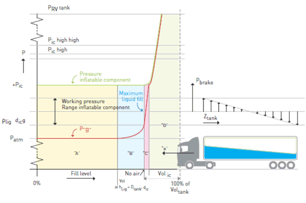
Legend with Figure 2.
The relationship between the liquid fill level of a tank (x-axis) and the pressure (y-axis) in the liquid, red line, and in the inflated component, green line, is shown on left. The accommodation of pressures resulting from breaking and how these fit in the working range of the component is shown on the right.
Symbols and remarks in figure, refer to text.
Figure 2. Graph showing the relationship between the liquid fill rate of a mobile tank, the pressure within a fixed volume inflated component, and the outside pressure in the liquid at the lowest point of the inflated component.
In the liquid filling process, the following four stages can be identified:
• The "free ascension" level. (See "A", Figure 2.)
• The "last air delivery" level. (See "B", Figure 2.)
• The "only liquid compression" level. (See "C", Figure 2.)
• The "compression of liquid and inflatable components" stage. (See "D", Fig. 2)
2.2 Inflatable components with variable volume
Inflatable components of the variable volume type fill the entire mobile tank when there is no liquid inside, and therefore have the same (maximum) diameter as the diameter of the mobile tank in which they are used. This type of component allows the filling and discharge of liquid partial loads of tanks during a voyage, e.g. Milk collection at several farms or gasoline dispensing at petrol stations. The tank has no free air inside at any time.
2.2.1 Principle of functional operation
The principle of the functional operation is, firstly, that the material of the inflated variable volume component is always tensioned and that this tension changes relatively little during (external) pressure changes that may occur in the fluid (short term) during the liquid transportation. The variation in inside and outside pressure differences between liquid filling and constant volume transport conditions is used to retain the required material tension. See Figure 3 b. The second essential principle is that by the presence of a liquid cargo there is "too much" component material, i.e. more material than necessary to contain the amount of air. This "too much" material collects in "flaps", which become positioned against the inner tank wall. The liquid has the same pressure as the inflated variable volume component at the completion of liquid loading and during its transportation. These pressures and the additional hydrostatic pressures provide the possibility of high frictional force transfer between the component (flaps) and the inner tank wall whereby relative movements between these two cannot and will not occur.
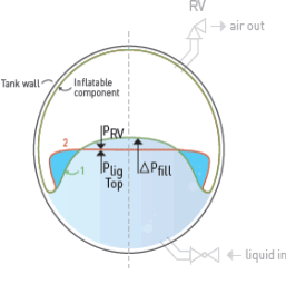
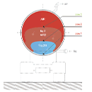
Figure 3. (a). Shows a cross section of a horizontal cylindrical tank in which a variable volume component is present. The contact area of the liquid and venting component increases during the liquid filling of the tank from position "1" through "2" to position "3". Figure 3 (b) The contact area between the variable volume component and the liquid surface changes from a curved shape to a (nearly) horizontal ("2") shape ("2") when the liquid ("1") is loaded the liquid filling process ends.
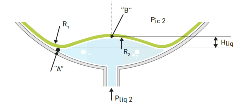
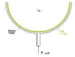
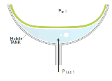
Figure 4. (a, b and c) Mobile tank without liquid, completely filled with inflated component, (left) With some liquid on pressure equal to component inside pressure, (middle) With more liquid on pressure higher than the inside pressure of the component (right).
2.2.2 Functional working method
At the beginning of the liquid filling process, the pressure at the liquid filling point of the tank will be atmospheric because the pressure in the inflatable component is "Pic" (higher). Refer "K" in Figure 6.
At the beginning of the filling process, the pressure in the liquid must first build up to the same pressure as in the inflatable component "Pic". See Figure 4 a. and refer to "L" in Figure 6. As the pressure difference across the wall of the component decreases, the component material loses tension and hence the radius of curvature. The liquid already flows into the tank but no air is expelled from the inflated component yet. Refer to "F" in Figure 6. When the fluid pressure has increased and has become the same as the internal pressure of the component, the component material is locally flat. See Figure 4 b.
As the pressure in the fluid continues to rise and becomes higher than the internal pressure of the component, the material will bend inward on contact with the fluid. See Figure 4 c. This further increase in pressure in the inflated component progresses until the pressure relief valve reaches its lowest (set) value. At this point, "PRV open", the inflated component begins to expel air. Refer for the liquid position after "M" and for the air in the component after "G" in Figure 6.
Pressures and flow rates increase until a balance is achieved, with liquid in the tank and air in the component both having the same pressure "ΔPfill" and the rate of the air flow from the component is equal to the inflow rate of the liquid into the tank. Refer to "N" in Figure 6. Reducing the air volume of the variable volume component causes the component material to "become spare" and to collect in "flaps" that form on the inner tank wall, see Figures 3 a and b.
At each liquid level, the liquid filling process can be stopped, even before the tank reaches its maximum (100%) fill. The overpressure in the liquid "ΔPfill", required to allow the liquid to flow into the tank and to displace the air from the inflated component, falls back to "PRV open", where the pressure control valve closes and the liquid velocity drops to "0". Refer to the course of "N" to "G" in Figure 6. The liquid is then at pressure "Ptransp. 1 ", see Figure 6, at which the liquid is transported.
The surface of the liquid and the local component of the surface form from (slightly) curved to (almost) flat, because the center of gravity of the liquid repositions to the lowest possible position. The associated gravity energy reduction is converted into an equal increase in "spring" energy of the material of the component as the material of the component stretches further. At the same time, when "ΔPfill" starts to fall, air is forced out of the "flaps" by the hydrostatic forces of the liquid. The contact surface between the outer and inner side of the flap material increases and allows the transfer of considerable frictional forces, while not allowing for relative movements. This prevention of the movement of "flaps" component material causes the material to remain tensioned at the nearly horizontal contact surface of the fluid and component. The "flaps" are pressed by the hydrostatic pressure further against the inner wall of the liquid holder, see also Figure 5.
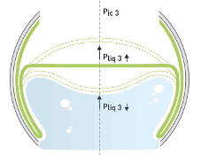
Figure 5. Behavior of the contact surface between liquid surface and component upon further partial filling or discharge.
Refer to "Q" in Figure 6. Once the discharge stops, the pressure in the component will rise to the point ("R +") with the air pump shutting off. Further transport of the remaining liquid is then at the pressure "Ptransp. 2 ", see Figure 6, take place.
When taking a partial load, in case the mobile tank is already partially filled and even may remain partially filled, and when unloading a partial load, in case the mobile tank is partially filled and even may remain partially filled, functional working methods proceed like mentioned above. References to Figure 5. Note: For loads of additional partial loads, "L" shifts to the high of "Ptransp. 2 "and the curve between" L "and" M ", see Figure 8, is bent more and more because of the decrease in the volume of the component, conforming to formula (9). For discharges of further partial charges, the curve between "Q" and "R +, Ptransp. 2 ", Figure 8, becomes more and more flat, because of the increase in the volume of the component, also again in conformance with formula (9).
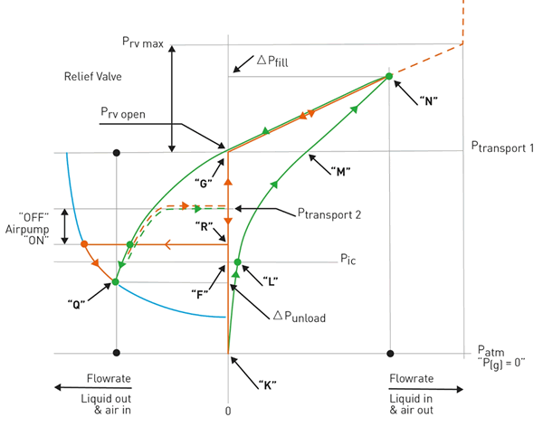
Legend with Figure 6.
The “green” lines in this graph reflect the relation between the liquid fill rate (in or out) of a tank and the pressure development in the (top of) the liquid. The “orange” lines in this graph reflect the relation between the pressure in the inflated component and the airflow in or out of the component. The continuous lines reflect a process starting with an empty tank with filling until a maximum level and vice versa. The “dotted” lines in both colors reflect a situation in which liquid is added or withdrawn from a tank with a partial cargo.
Figure 6. Graph showing the relationship between the charge and discharge rate of a liquid cargo of a mobile tank, the pressure within an inflated variable volume component, and the liquid pressure.
2.2.3 Basic formulas
The length of the component is similar to that in the solid volume component, see formula (1).
The volume of the component is always the balance of the tank and liquid volume:
Vic = Vtank - Vliq (3a)
The maximum diameter of the component, "dic max" is equal to the tank diameter: (dic max = Dtank, (8))
which diameter is achieved with an elongation of the material of preferably 0.1 to 0.5% to guarantee that the material of the component meet the functional necessary requirements. For this purpose, formulas (4) and (5) are used. An elongation of less than 0.1% increases the risks of component production accuracy. An elongation of more than 0.5% requires an unacceptable low Young's modulus "E" of the material of the membrane walls.
To calculate the curves during loading and unloading, formula 4 is to be used. The curves and their radii of the component material that is in contact or comes with liquid change, from the initial position during loading, see Figure 4 a. to the position where the overpressure valve starts to blow air off, see Figure 4 c. The volume change of the component "ΔVIC" is hereby calculated using:
Vtank PIC = (Vtank - ΔVIC) (PIC + PRV open) (9)
Theoretical pressures in the liquid are always at the highest point of the liquid, see "B" in Figure 4 c. Forces for diffracting the material, according to material properties, are additionally in places of the contact surface, such as "A" in Fig. 4 c.
The width of the contact surface "W" of the component with the liquid surface depends on the degree of filling, where: 0 <W <Dtank. The extension of this contact surface "εW" is thus dependent on the liquid filling level of the tank. The "εW" decreases when the width of the contact surface increases. The lower tension in the material resulting from a smaller "εW" is functionally compensated by less force being required to open the flaps in a near 50% liquid filled tank. The flaps are in an about 90° angle with material in the liquid contact surface when the tank is about half full. Commencing discharging or loading of liquid meets with less resistance (pressure difference requirement) the nearer the tank is to a 50% liquid-fill. The flaps “open” easier.
3. Results and conclusions on traffic safety

Figure 7. Pictures of tank trucks in which Cairbags were tested and of third-party tank trucks in which first Cairbags were applied.
3.1 Braking
The brake-related pressure that occurs in the fluid between the front plate and the rear plate of the mobile horizontal cylindrical tank is calculated as follows:
ΔPdec = ρliq Ltank adec (10)
The pressure in the liquid on the front panel increases by ½ ΔPdec, while the pressure drops by ½ ΔPdec on the rear panel. See also Figure 2. The results of the braking tests confirmed convincingly that both the means of transport and the liquid cargo, partially filling the tank were completely and simultaneously in a completely stable condition and dominated by the truck driver.
From the first moment of complete standstill, the trucks with liquid cargo securing, as used in the tests, were not subject to any vibration or movement. Sloshing of a liquid cargo and vibrations and movements of a tank truck are common to continue until several minutes after such truck has “stopped” when no liquid cargo securing is applied. In these situations, the liquid oscillates for a much longer period than the time the truck needs to come to a standstill. The absence of any movement or vibration when the tanker came to a stop was the most obvious evidence that the fluid did not move relative to the vehicle.
Another striking feature is the increase in the braking distance of a tanker with a liquid load-securing component. The brakes of the tank trucks must also absorb the kinetic energy of the liquid cargo during braking and not just the kinetic energy of the vehicle as in the case without load securing. This extension of the braking distance was confirmed during the tests (which for safety limitations could only be done up to speeds of 40 km/hr).
During braking, pressures in the fluid occur according to formula (10). The component radius changes from front plate to rear plate and related volume change can be calculated using comparison (4). As the pressure in solid volume component; Pic> ½ ΔPdec and as the Young's module the material is high by design, the deformation of the component is negligible. Such minor change of the form and volume of the component causes very small and semi-static movements of small volumes of liquid. This will have no noticeable impact on the stability of the tank vehicle. Similarly, with variable volume components, the pressure differential across the material changes, causing the stress in the material to change. As de Young's module, the material is high, the movements of the liquid will be very little here and have no noticeable effect on the stability of the vehicle.
3.2 Driving through curves
The deformations of the inflated component, either a fixed or variable volume, are small and, according to the changes in the pressure difference between the inside and outside of the component, the same as in "braking", see above.
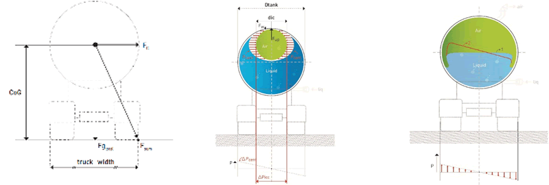
Figure 8. (a, b and c) Cross section (left) of the mobile tank as used in the theoretical model. (center) with a fixed volume inflated component exposed to centrifugal pressures. (right) with inflated variable volume part and extended contact surface on top of liquid.
A liquid-filled tanker (see Figure 8) passing through a curve of constant velocity "v" and radius "r" is exposed to total centrifugal forces "Fc total". This "Fc total" is the sum of the centrifugal force "Fc liq" of the liquid of mass "mliq" located in the center of gravity of the liquid "CoGliq" and the centrifugal force "Fc truck". of the empty lorry "with the mass" mtruck ", positioned in the center of gravity of the empty lorry," CoGtruck ".
Fc total = Fc truck + Fc liquid = (mtruck + mliq) v2 / r (11)
In general, the tanker does not tip, see Figure 8, assuming:
Fg total ½ Wtruck> Fc total CoGtotal (12)
Fg total = Fg truck + Fg liq = (mtruck + mliq) g (13)
and where "Wtruck" is the width of the truck (on the axle from and to the outside of the wheels), see Figure 8.
The condition "critical overturning" is reached at "vmax" if:
v2 = (½ Wtruck / CoGtot) r g (14)
Tabel 1. Maximum Speed in Curves for different liquid behaviour conditions. Four "example" cases provided a basis for evaluating and comparing the effects of different mobile tank conditions on the possible, but not "toppling over" maximum speed. This table shows the results of these maximum speeds with which a mobile tank can make a turn.
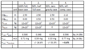
Legend for table 1:
• Case 1: The comparison reason is a 100% liquid filled mobile tank.
• Case 2: Shows the maximum speed of a 50% liquid filled mobile tank
• Case 3: The maximum speed of a 50% liquid filled mobile tank with "skipping, weightless" fluid.
• Case 4: The maximum speed of a 50% liquid and 50% inflated component filled mobile tank shows.
3.3 Evaluation of safety benefits for normal driving conditions
Table 1 shows the maximum speed at which a tank-truck, as shown in figure 8 a., can drive through a curve with radius “r” for four different liquid behaviour conditions. The base case as in Column “1” is a truck with a 100% liquid filled tank which can drive at a maximum speed of “0,71 √r g”. At a higher speed it will keel-over. This maximum speed drops by some 16,6% in case the truck is half liquid filled (i.e. 50% full) and the centre of gravity of the liquid moves semi-statically to its most outward position, as shown in column “2”. This maximum speed, with a 50% liquid filled tank, drops much further to over 50% (!) (53,3%) in case the truck is half liquid filled (i.e. 50% full) and the liquid progresses into a roll-over wave in which its temporarily “weightless”, as shown in Column “3”. Note: This condition was recorded at one of the test drives performed by the TÜV tests. A Cairbag application, in the 50% liquid filled case, ensuring the centre of gravity of the liquid to remain at its lowest point results in an 8.6% higher possible maximum speed, see Colomn “4” in table 1, as compared to the 100 % liquid filled tank condition.
An entirely "weightlessness state" of the liquid as in column "3" may be "unlikely". As weightlessness of part of the liquid will occur, mostly subject to driver steering and acceleration actions, the maximum speed will be within the range of values calculated by column "2" and column "3"; 0.33 √rg <vmax <0.59 √rg or 46.7% <vmax <83.4% of vmax basis. The results were also obtained for horizontal cylindrical containers with an oval instead of circular cross-section. Refer Eenkhoorn EJ, 2017. Results for oval tanks are some 20% worse than those shown in table 1 for circular, horizontally shaped mobile tanks. Baffles do not offer any sideward stability.
3.4 Evaluation of safety benefits and the reduction in severity of accidents
Securing liquid cargoes also reduces the serious consequences of very heavy accidents, especially of tank-trucks transporting (pressurized) liquefied gas. The fluid dynamics associated with an immediate stoppage of a tanker truck, such as a head-to-tail accident, causes pressure spikes that may occur, for example, at the position of the high-pressure safety valve or the nearest manhole cover. The pressure may be higher than the valve set pressure for a short but sufficiently long moment. As soon as such a device provides an opening, vapours are directed from the tank to the outside where there is too often already a fire on-going. Such external fires may often be the cause of the unprotected, single thin hulled, truck diesel tank failing in the accident and the diesel catching fire. The safety valve is damaged and therefore no longer "closes". The fire will now continue for a long time fuelled by the unrestricted outflow of gas from the tank. The liquid gas remaining inside the tank will commence to boil causing a catastrophic BLEVE. Reference https://youtu.be/fWY7jqQvfJU. The risks of exposure of tank components, especially the overpressure protection devices, to high, liquid dynamic based, pressures are eliminated by Cairbags.
Final Conclusion
Liquid load securing has many advantages. Significant advantages result from direct safety improvements of current day-to-day bulk liquid transportation. Additional advantages result from accident mitigation improvements. Using inflatable components to secure liquid cargoes results in further environmental advantages as the cargo cannot evaporate, hence there are no vapours which may be emitted. ADR mandatory baffles do not secure liquid cargoes. By their permanent installation in mobile tanks, these baffles continuously dampen the liquid, also in “non-braking”, normal driving situations of a tank truck. This constant dampening of the liquid by baffles causes adverse effects on the fuel consumption by the truck and thereby on CO2 environmental emissions.
Liquid load securing should at least be allowed but, logically, should be made mandatory identical to the securing of any other cargo.
Acknowledgments
• The independent German certification body TÜV Nord for the certification of mobile tanks equipped with inflated components meeting ECE-111 and thereby ADR requirements.
• The independent Dutch testing and certification organization TNO for the validation of Slosh mitigating models.
• The Dutch fuel consumption specialist "Supro" for the targeted recording of fuel consumption during the tests.
• The “Punt” company for the first practical fixed volume Cairbag application.
• DEA (Deutsche Erdöl Aktiengesellschaft) on the application of the first variable volume ADR-based surge avoidance system, the beneficial "zero-emission" survey of its tests and the accompanying paper on "Cairbag" development, such as the DGMK Spring Meeting, 18/19. April 2018 in Celle (Germany).
References
Eenkhoorn, E.J. (2017). Products to mitigate liquid sloshing, University of Twente, Enschede The Netherlands. ISBN 978-94-6233-808-1. Further reference is made to all references herein.
United Nations Economic Commission for Europe, European Agreement concerning the International Carriage of Goods by Road ("ADR"), Geneva, 30 September 1957